
The board also supports I2C cascading, allowing the use of multi modules connected to the I2C bus at the same time by connecting the pinheader and connector. Hence, it’s more flexible to connect the board to your development system. The PCF8574 IO Expansion Board features an I2C pinheader on one side and an I2C connector on the opposite side. Up to 8 PCF8574, IO Expansion Board can be connected to the I2C-bus, providing up to 64 I/O ports. The PCF8574 IO Expansion Board is used as a remote 8-bit I/O expander for I2C-bus.

PCF8574, I2C interface, 8-bit parallel port This script is meant to be used by people who want toĬreate parts for the libraries.Modulo-expansor-io-pcf8574 1200×1200 90 KB unitconverter.pyĪ simple script and wrapper around the functions that convert coordinates This repository provides a library of OpenSCAD models thatĬan be used to create the model. So fzz2scad simply dumps everything on the PCB to the file.Ī file that contains all the necessary modules to render the model, canīe compiled. OpenSCAD ignores modules it does not know, Parts Librariesįzz2scad does not do much by it self, it simply extracts and transforms $ python fzz2scad.py testing/some_buttons_leds_and_a_switch.fzzĬreating A Model (or Frontplate) from a Sketchįor a step by step introduction see the HowTo. (see: scadlib and scadlib-electronic-components )

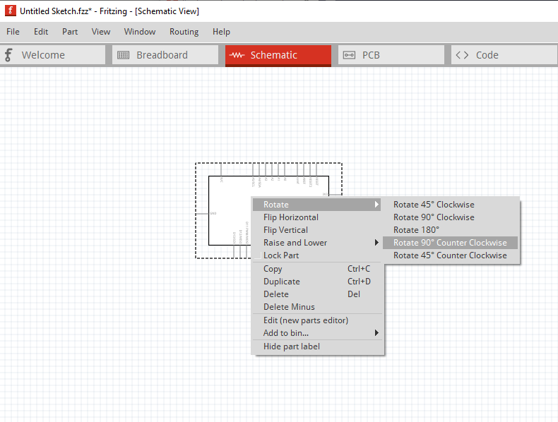
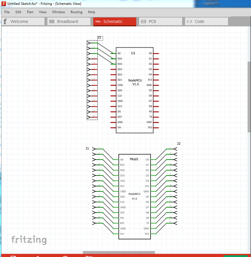
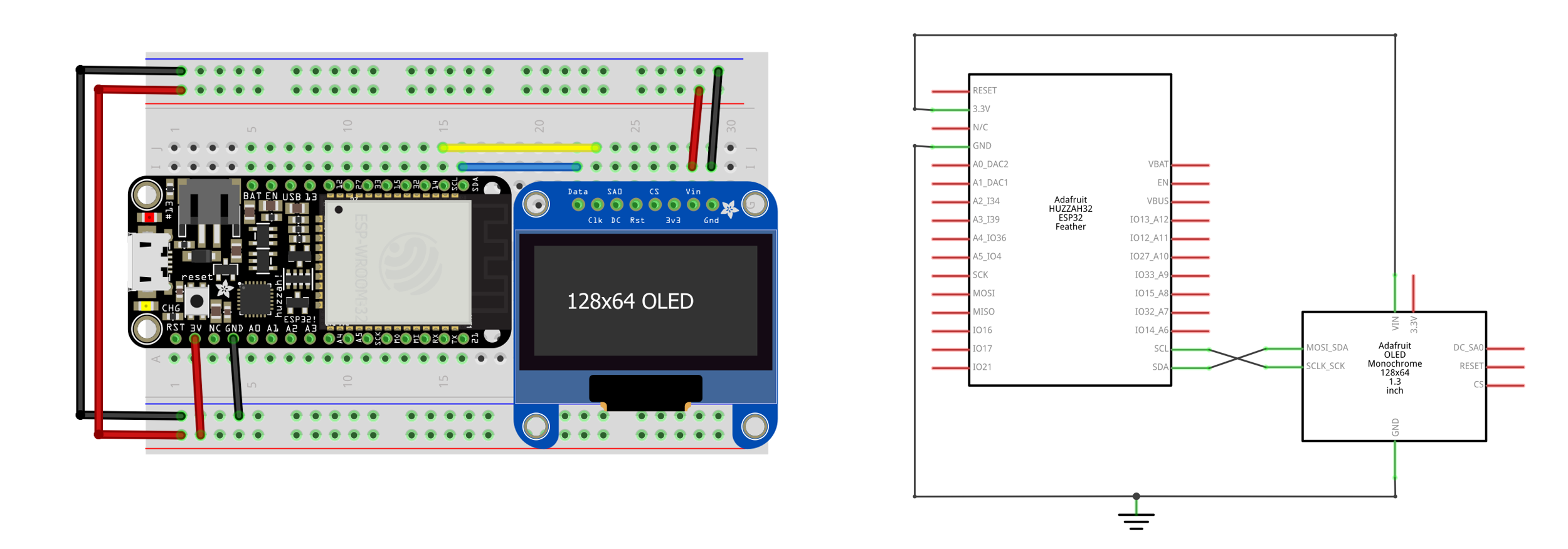
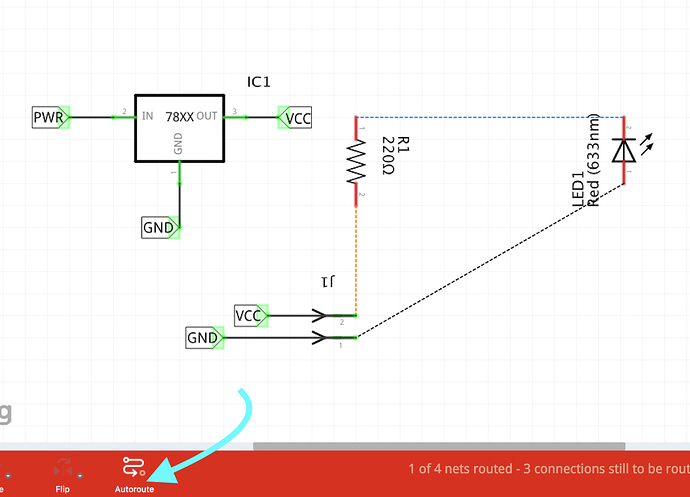
Fritzing comes with a Core bin which features a nice collection of parts, but it also lets you create your own part bins ('Mine' bin), so you can organize core and custom parts any way you want.

They might also be used to create complete 3D-Models of a PCB -ĭepending on the parts library used. The Part Library has a selection of electronic parts that you can directly drag and drop to the Project View. The models are meant to be used to create front plates for 3D-Printed casings. Create a 3D Model/Frontplate (OpenSCAD) of/for the PCB in a Fritzing Sketch.


 0 kommentar(er)
